
One FCU test moved from a full bench day to a short operator run.
RF ATP Stand for FCU Production Test
This production acceptance-test stand turned a hands-on Frequency Conversion Unit test into a repeatable technician workflow: connect the cables, enter run information, press go, and receive clear pass/fail results with supporting documentation already generated and stored.
Automated instrument control
Broad RF measurement coverage
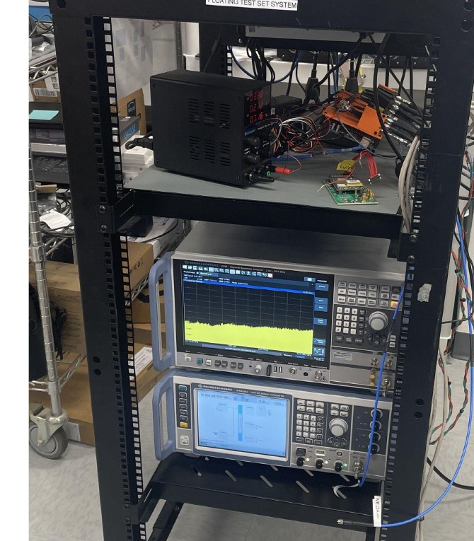
Portable RF production test rack built for a space-constrained lab environment, with instrumentation, switch hardware, fixture electronics, and technician-facing control.
The technician does not need to manually drive instruments or open reports.
Reports, analysis images, zipped data, and failure summaries are generated automatically.
Test artifacts are packaged, sorted, and stored for review without manual file handling.
Project overview
A hardware team needed production acceptance testing for a Frequency Conversion Unit (FCU) that was simple, automated, repeatable, and difficult to operate incorrectly. The stand was designed around a compact footprint: small enough to move, clear enough for technicians, and structured enough for consistent production use.
The final system automated equipment setup, FCU communication, RF path selection, measurement collection, documentation, pass/fail display, cloud storage, and SharePoint sorting. For the operator, the workflow was reduced to a few clear actions while the stand handled the test sequence and records automatically.
Primary goals
- Make acceptance testing repeatable and difficult to run incorrectly.
- Remove cable moves and manual instrument setup wherever possible.
- Show all pass/fail results without forcing technicians to open documentation.
- Automatically generate the acceptance-test record, analysis images, zipped data, and failure summaries.
- Keep the stand compact enough for changing lab and production needs.
System architecture
The RF path was built to avoid repeated manual cable movement while preserving the flexibility needed for each acceptance-test measurement.
Hardware topology
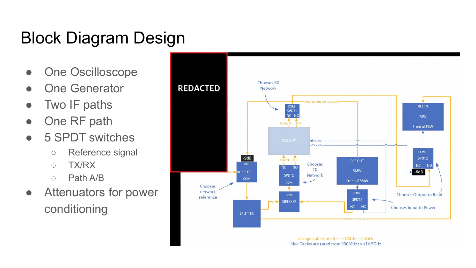
- Instrumentation One oscilloscope and one RF generator formed the core measurement and stimulus hardware.
- Signal routing Two IF paths, one RF path, and five SPDT switch positions selected the reference signal, TX/RX mode, and path A/B routing.
- Power conditioning Attenuators conditioned signal power so the stand could move between test cases without unsafe or inconsistent levels.
- Switch hardware A relay board and RF switch hardware exposed the routing network to software control.
Block diagram design
Switches selected the reference, transmit, receive, and output paths while the stand routed RF and IF signals through the FCU acceptance-test flow.
Control workflow
The stand combined a technician-facing desktop UI with automated instrument and switch control running in the background.
Technician UI
Guided operator control
The laptop application collected run information, offered full-sequence or targeted-test modes, and showed pass/fail status without requiring the technician to open the generated report package.
Automation layer
Device, instrument, and switch control
Control software coordinated the FCU, RF instruments, and switch network so setup steps, routing changes, and measurement capture could run consistently from one workflow.
Measured tests
Full acceptance-test coverage
The application could run the complete FCU acceptance sequence or individual checks as needed. ACLR, EVM, and phase noise were part of a broader measurement set, with each result captured alongside the supporting artifacts for review.
Generated deliverables
Each run produced the acceptance-test record, review-ready analysis images, zipped raw data, and a failure summary when limits were not met. Results were synced to cloud storage, and the report package was sorted into SharePoint automatically.
Acceptance record
Analysis images
Zipped data
Failure report
Incremental automation results
The project was built in phases, with each layer removing another source of manual setup, data handling, or operator error.
No automation
8 hr
Reusable instrument profiles
5 hr
Instrument-control scripts
2 hr
RF switching hardware
1.5 hr
Report and image automation
30 min
SharePoint sorting
15 min
The compounding payoff
The first improvements reused instrument profiles and scripted setup, but the biggest usability gains came from removing cable moves, automating document assembly, and automatically placing the finished records in the right storage location.
By the end, a unit that previously took 8 hours to test could be completed in 15 minutes. The technician only had to connect the cables and press a button.
Result: A production test process became faster, more repeatable, and easier to hand off to technicians while preserving measurement depth and documentation quality.
Project value
A production tester like this turns specialist bench knowledge into a controlled, repeatable workflow.
Engineering value delivered
The stand combined RF system integration, switch network design, test sequencing, desktop tooling, instrument automation, report generation, and cloud storage into one production-ready workflow.
Where this applies
- RF production acceptance testing
- Manufacturing test fixtures for high-mix hardware
- Validation benches that need repeatable documentation
- Lab and production test stations that must stay compact and movable
Need an RF test process automated?
Laztronics builds practical test stands, custom control software, and documentation workflows for hardware teams that need reliable validation without repeated manual bench work.