
Step 1
Build the baseline calculator
A MATLAB calculator was built to compute unequal-split Wilkinson impedances and produce layout oriented outputs, including trace widths and quarter-wave lengths from user inputs.
The primary objective was to build a MATLAB calculator for unequal Wilkinson divider design, then validate it with a 4:1 divider at 2.4 GHz. During validation, the standard unequal model proved insufficient for practical layout, so the calculator was extended to include quarter-wave transformer sections and comparative analysis between both designs.
The core deliverable was a custom MATLAB calculator for unequal Wilkinson divider synthesis. A 4:1 unequal divider at 2.4 GHz was then used as the validation case to verify the calculator outputs against simulation and layout behavior.
The calculator accepts system impedance, split ratio, operating frequency, substrate permittivity, and substrate thickness. It returns transmission line impedances, resistor value, and physical layout parameters including trace widths and quarter-wave lengths.
Validation started with the standard unequal Wilkinson model. When that model produced impractical electrical conditions for this split ratio, the calculator was updated to include quarter-wave output transformers, and both approaches were analyzed side by side.
Many online unequal-split calculators stop at intrinsic transmission line impedances. This workflow extends further by calculating physical trace widths from those impedance targets for immediate PCB layout use, while noting that not every computed geometry is practical to fabricate.
Calculator development, simulation-backed validation, and microstrip-oriented output generation.
4:1 unequal split at 2.4 GHz with strong matching and isolation behavior.
The standard unequal model can become impractical for larger split ratios without topology refinement.
Calculator outputs still require engineering review because some resulting dimensions are not always practical to fabricate.
The workflow moved from calculator creation to validation, then model refinement and comparison.
A MATLAB calculator was built to compute unequal-split Wilkinson impedances and produce layout oriented outputs, including trace widths and quarter-wave lengths from user inputs.
The calculator was validated by implementing a 4:1 divider at 2.4 GHz. Analysis of the standard unequal model highlighted impedance extremes and layout practicality issues for this split ratio.
The calculator and network were updated with quarter-wave output transformers, then baseline and refined designs were compared using S-parameters, split ratio, and microstrip feasibility.
These performance and implementation values define the design target and the final engineering constraints.
Validation showed why the baseline model was insufficient and why transformer assisted refinement was needed.
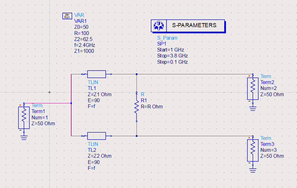
For a 4:1 split, the simple unequal divider pushes one impedance path to an impractically high value. A representative baseline case produced 1000 ohm for Z1 with 62.5 ohm for Z2, which is theoretically valid but difficult to implement cleanly.
With output transformers added, the divider achieved very low reflections and strong isolation around 2.4 GHz while preserving a power ratio near the target. The transformer assisted network reached roughly P3/P2 = 3.9967, and the microstrip layout still held close at P3/P2 = 3.9958.
The project delivered a practical calculator workflow: generate electrical targets, convert them to layout dimensions, validate in simulation, and refine the model when outputs are not physically practical.
Summary: A MATLAB calculator was developed and validated on a 4:1, 2.4 GHz divider; baseline limitations were identified, quarter-wave transformers were added, and both designs were compared to balance electrical performance with layout practicality.
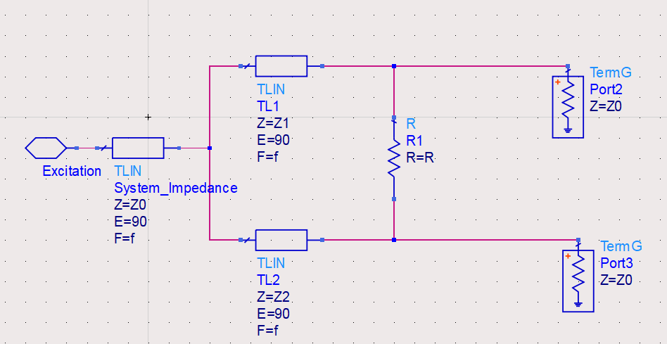
Baseline unequal divider schematic used for initial network synthesis.
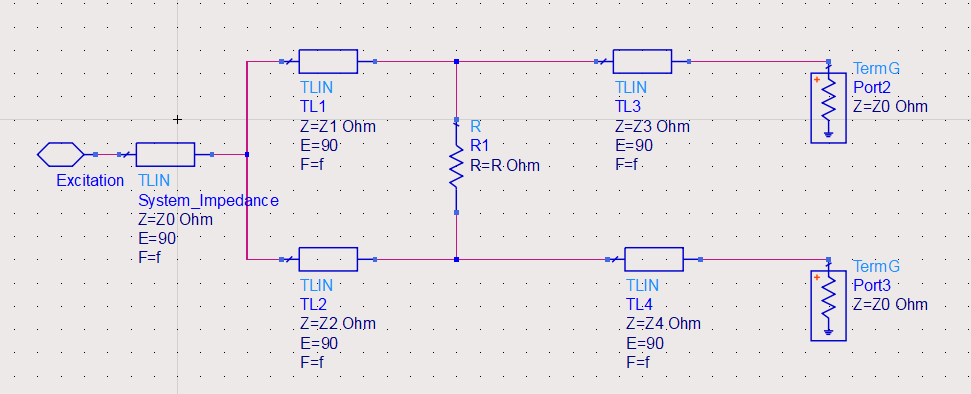
Refined topology used to improve matching and isolation while retaining split ratio.
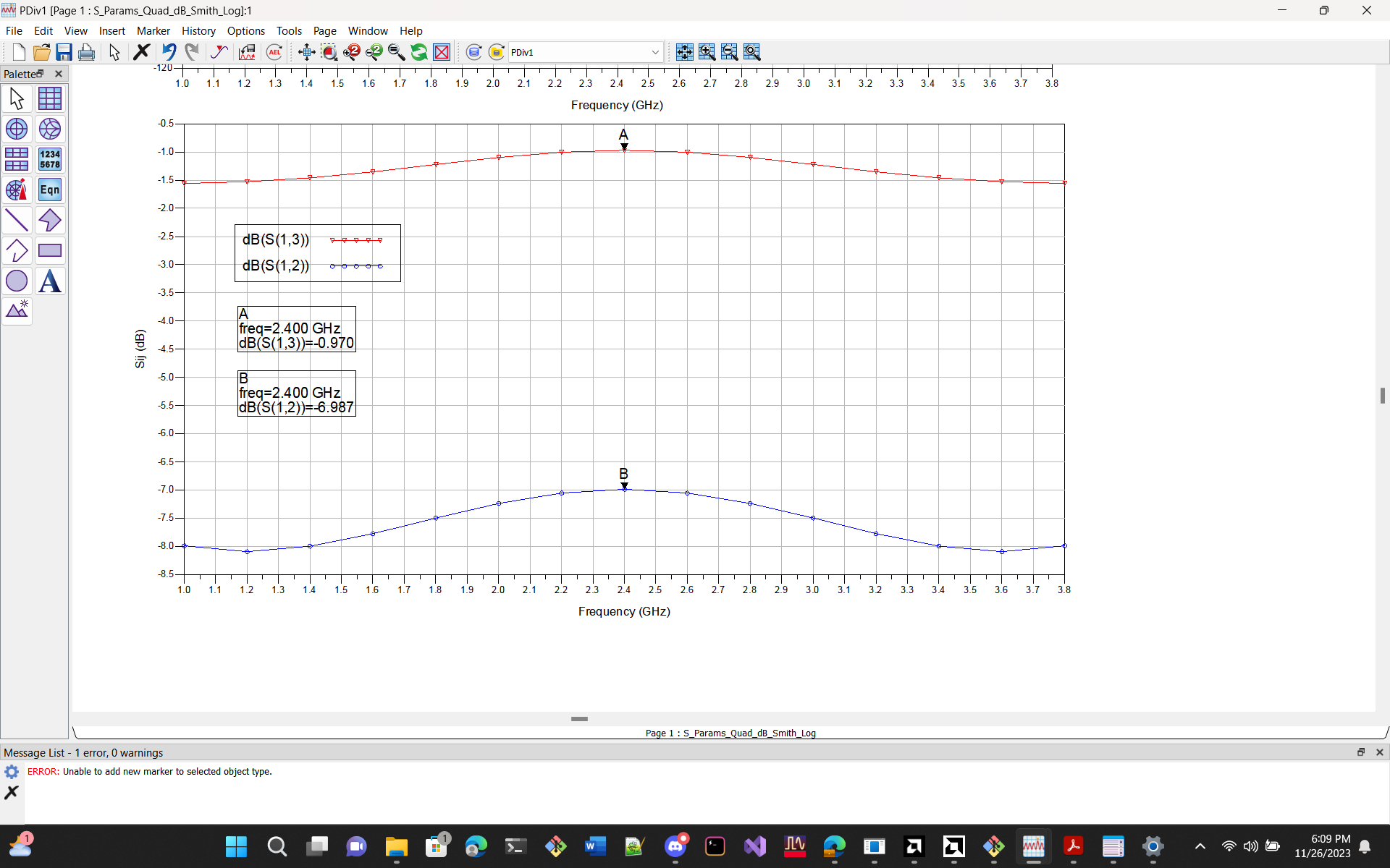
S-parameter response of the baseline network, including match and isolation limitations.
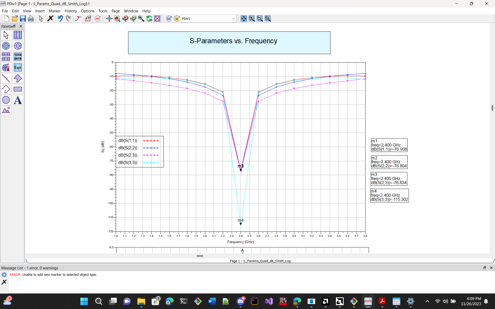
S-parameter response of the refined network, showing improved return loss and isolation.
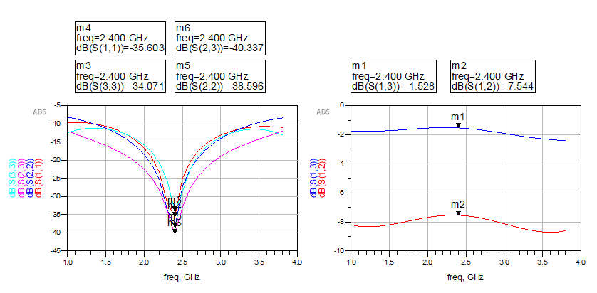
Side-by-side comparison of port metrics and output power ratio across design stages.
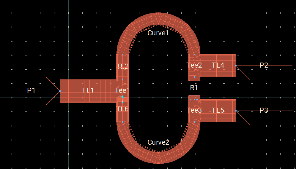
Physical layout used to validate manufacturability and layout level RF behavior.
Applicable to RF front-end development programs that require split accuracy, isolation, and layout realism.
Delivered a custom MATLAB calculator for unequal Wilkinson divider design, then validated it with a 4:1, 2.4 GHz implementation and a side-by-side comparison of baseline and transformer assisted models.
Engineering scope included impedance synthesis, trace width and length generation, model refinement with quarter-wave transformers, and feasibility screening for physically practical layouts.
We support RF design, simulation, layout optimization, and test workflow development for teams building reliable wireless hardware.