
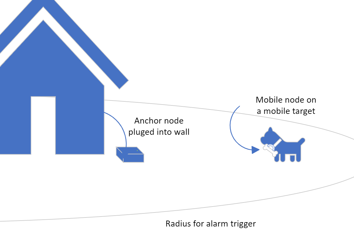
Core use case: an anchor node monitors a mobile node attached to a tracked animal and triggers an alarm when the target moves beyond the intended radius.
This is a two-node Bluetooth Low Energy tracking system focused on a robust mobile node for animal tracking. The same custom PCB architecture can be configured for either the battery powered mobile node or the wall powered anchor node, with RSSI-based geofence alarms in real time.
FIDO was designed as a Bluetooth Low Energy geofence for animal tracking. The system uses two cooperating nodes: a battery-powered mobile node attached to the tracked animal and a stationary anchor node that continuously scans for advertisements and decides whether the target is still within range.
The most interesting part of the project is that it combines embedded firmware, BLE communication, custom PCB design, battery charging and regulation, and real-world validation into one product-style prototype. The custom PCB was intentionally designed to be reusable across both mobile and anchor roles.
Measures proximity from BLE RSSI and triggers an alarm when the mobile node crosses the allowed boundary.
Custom NINA-B306 node hardware, a shared PCB for mobile and anchor builds, BLE firmware, battery charging, and enclosure integration.
It shows the full path from concept to firmware to PCB to packaged prototype instead of stopping at breadboard demos.
Low power IoT product development with practical engineering decisions around noise, false alarms, manufacturability, and battery life.
The mobile node periodically broadcasts BLE advertisements, while the anchor node continuously scans and processes RSSI to estimate whether the target is inside or outside the permitted range.
Because the mobile node rides on battery power, the firmware had to balance responsiveness with energy efficiency by advertising in bursts instead of transmitting constantly.
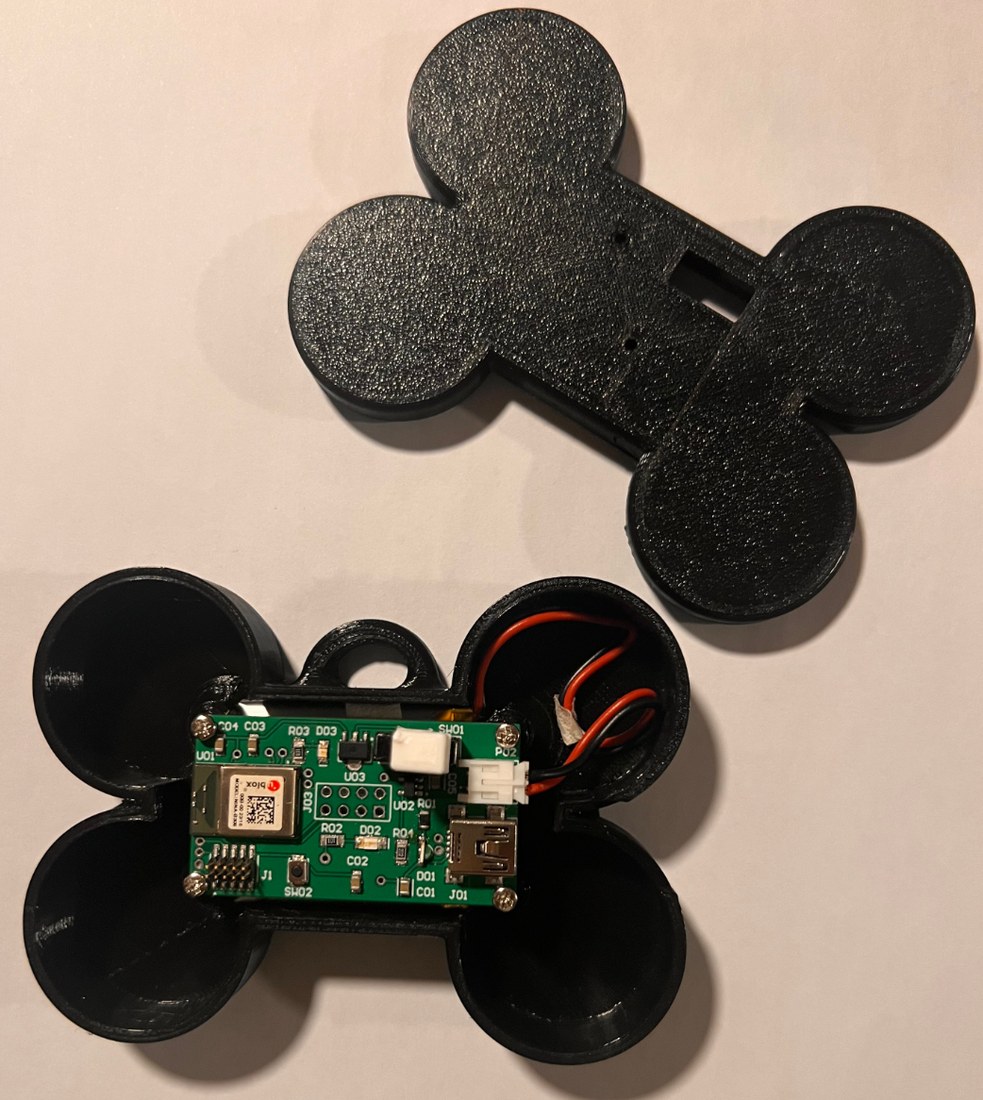
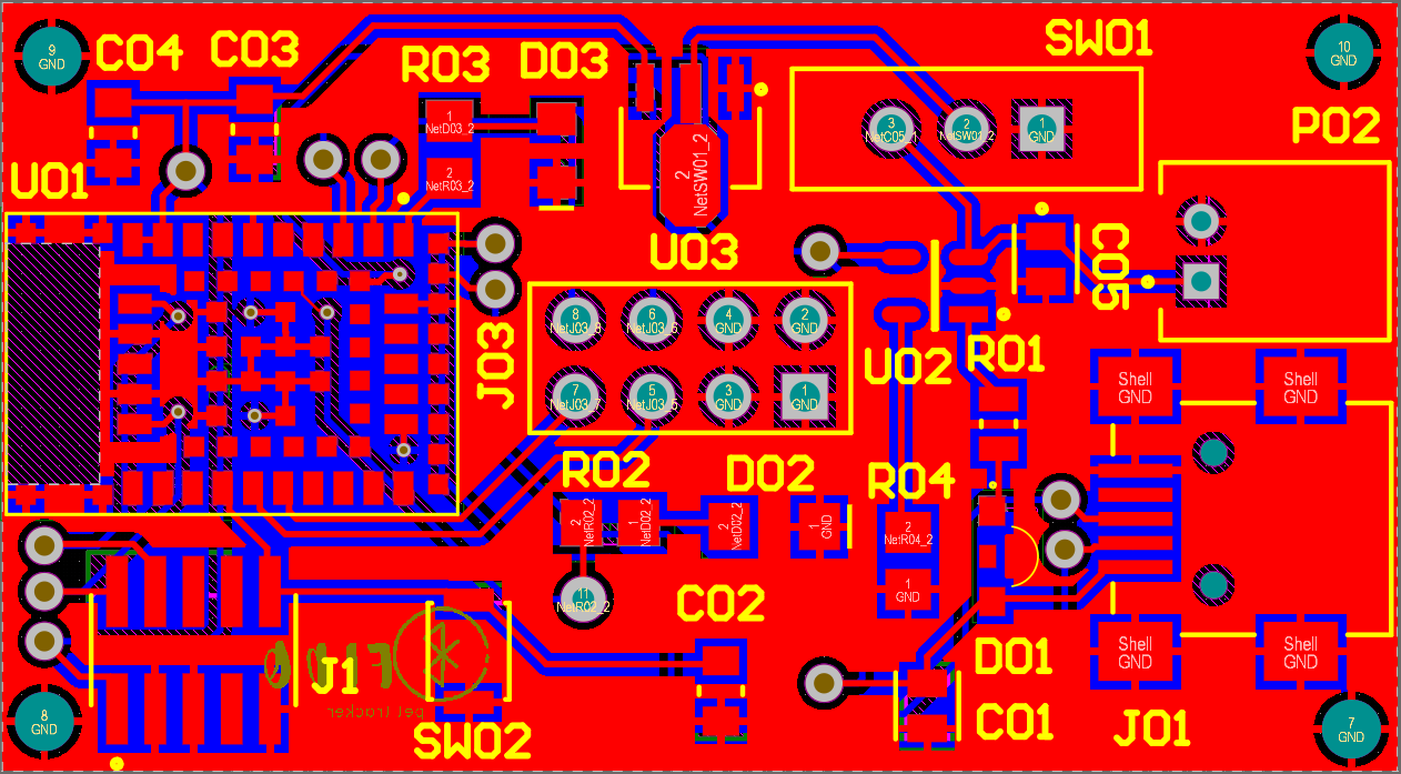
The design moved beyond development boards into a custom PCB built around the NINA-B306, a battery charging IC, a 3.3 V regulator, SWD access, status LEDs, and purpose-built enclosures. The same base PCB can be used for both the mobile node and the anchor node with role specific power and packaging.
The hardest part was not just basic Bluetooth communication. The project also had to manage RSSI instability, false alarms, battery life, charging and regulation, and the transition from off-the-shelf development boards to a physically integrated PCB.
During development, the system gained additional GPIO and LEDs, a more usable SWD header, larger 0805 components for hand assembly, and a moving-delay / hysteresis strategy to prevent alarm flicker caused by RSSI scalloping and edge cases.
The strongest part of this project is that the final result was not just a communication demo. It became a low power, custom hardware prototype that was repeatedly validated in realistic use cases.
Prototype testing showed that the BLE link was workable but sensitive to environment and range, which is exactly what you would expect from an RSSI-based distance estimate. In a noisy test environment, testing showed usable range on the order of about 30 feet, then thresholding and alarm logic converted that noisy signal into a practical boundary decision.
The mobile node drew roughly 38 mW during transmission and only 66 µW while waiting, which supported the design goal of more than 50 hours between charges using a 1.9 Wh battery pack.
One of the most useful lessons from the project was that raw RSSI is not clean enough to drive alerts directly. The final design used hysteresis and moving-delay logic so the alarm would not flicker during scalloping, reconnect events, or momentary borderline readings.
Best one-line summary: FIDO turned a simple BLE tracking concept into a custom low-power hardware prototype that balanced responsiveness, battery life, enclosure design, and noisy real world wireless behavior.
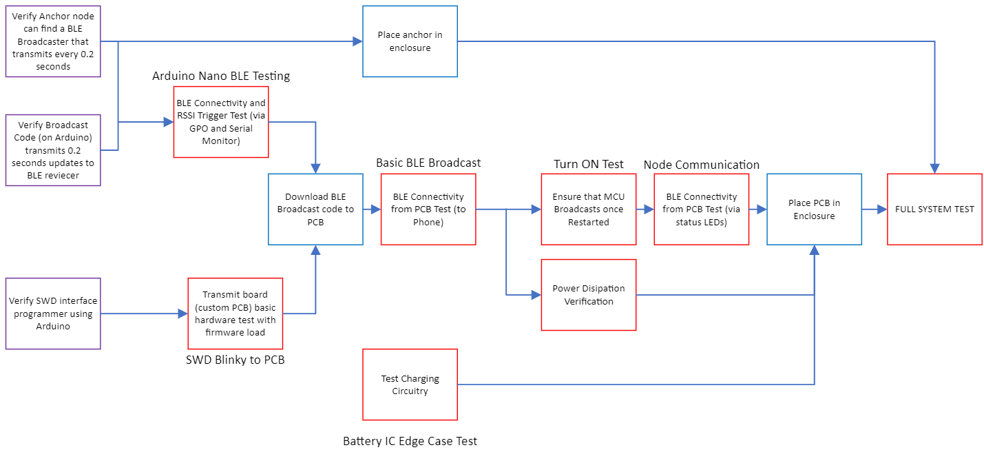
The project included staged bring-up tests for BLE broadcast, SWD flashing, charging behavior, power dissipation, enclosure integration, and the final full-system demo.
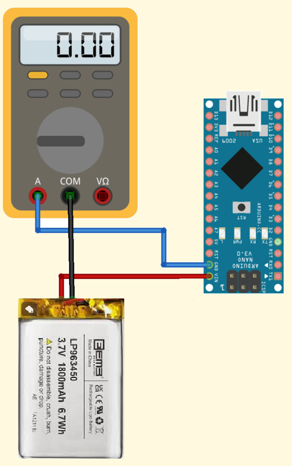
Power measurement was treated as a priority engineering requirement, not an afterthought, because battery life was central to the value of the mobile node.
The node hardware was condensed into a purpose-built board that can be used for both mobile-node and anchor-node builds.
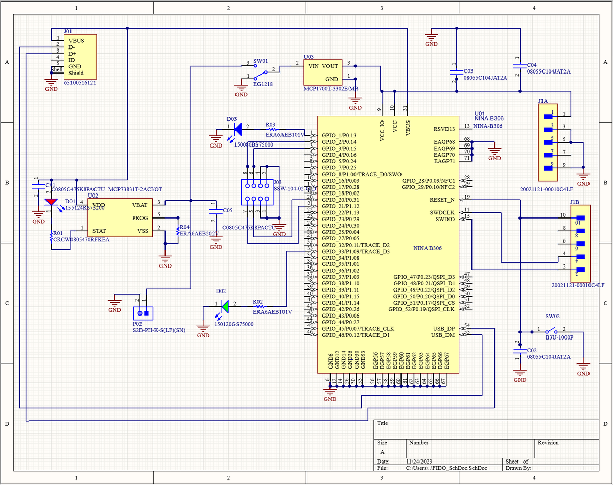
The design integrates BLE, charging, regulation, debug access, USB, and user facing indicators in a shared embedded hardware stack.
The bone shaped mechanical package makes the prototype feel like a real product instead of a lab only demonstration.
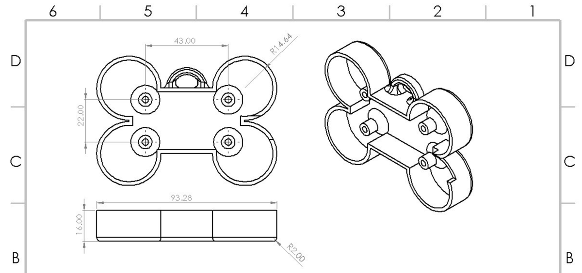
Mechanical design was part of the engineering story, including mounting geometry, packaged volume, and manufacturable assembly details.
If you need a low power wireless device developed end-to-end, support is available from architecture and firmware through custom PCB design, validation, and production ready documentation.